Overview
So the basic idea of the code is like this:
I set the USB interface to “Virtual Port Com” and read in the data I get into an array with a value for each output. Using arrays makes part of the code cleaner, but I can’t fully utilize on it. Some parts of the code deal with every value separately instead of iterating over the array, because it is faster and I have to try to run through the whole main code in one timer cycle. If I don’t I run into some problems (see below).
I will have a timer running at 250 kHz. It counts up to 5000 which means a full cycle will take 20 ms or a frequency of 50 Hz. This is the normal or traditional cycle time of an RC servo signal, so it should work with every servo or ESC. By reducing the max number the timer counts to, I can increase the frequency (for example count only to 1000 for 4 ms / 250 Hz cycle time).
250 counts will be 1 ms. With that I can control the pulse length from 1 ms (0%) to 2 ms (100%) in 250 steps. That is not much, but should be enough for my purposes and with a number of steps less than 255 I only have to use a single byte to set the pulse with of one output, which makes the communication protocol a lot simpler.
At the start of a cycle (with the timer at 0) all outputs are set high. If the timer reaches the count 250 + set pulse length for an output, this output is set low again. That means, if the pulse length is set to 0, the signal is high between count 0 and 250, which is 1 ms. If the pulse length is set to 250, the signal is high between count 0 and 500, which is 2 ms.
Settings and Configurations
Clock Setting
I’m using STM32CubeIDE for this project. The tool is quite nice for configuring the micro-controller, like setting the correct clocks or timers. The code writing on the other hand is a bit complicated. It auto-generates a lot of code for the user (which is basically all those settings done through the GUI) and leaves comments where the user is “allowed” to put their own code. These bits will not be overwritten in case the code is auto-generated again after changing some settings in the GUI. But I find that makes is sometimes a bit complicated to find the correct place to put code.
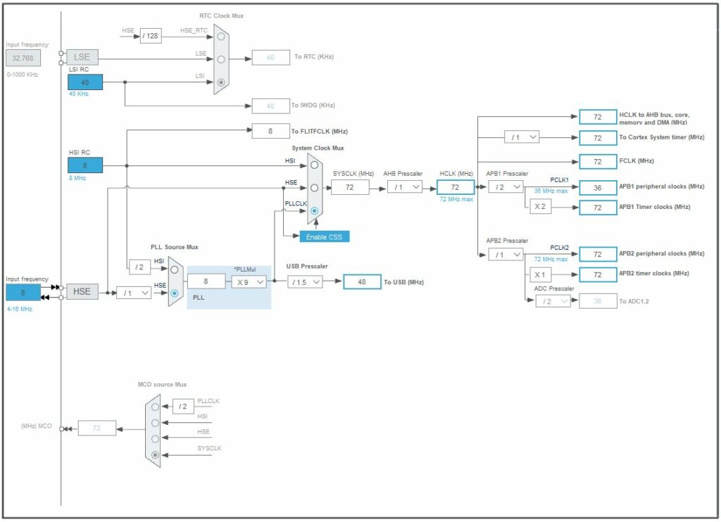
My board uses an external 8 MHz crystal, so I set that up as a source for everything else. Also I want the maximum speed from the micro-controller, so I set the PLL to run the whole thing at its max setting of 72 MHz. It needs a “USB Prescaler” of “/1.5”, since the USB has to run at 48 MHz.
IO Setting
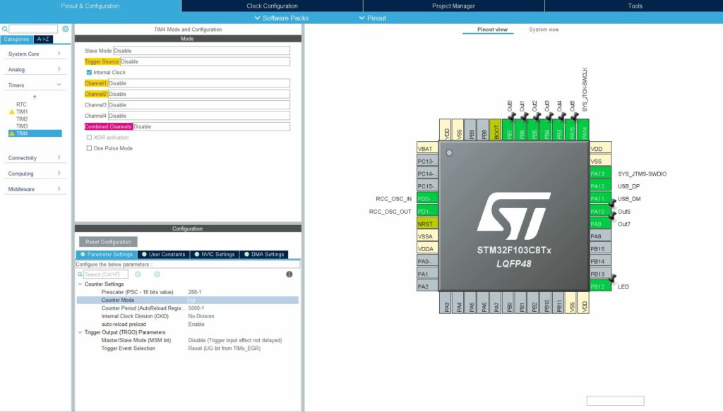
Eight pins I configured as outputs (PA9/10/15 and PB3-7) for the servos and named them “Out0” to “Out7”. From the layout of the development board it would have been good to use PA11/12, but those are reserved for the USB interface, so they can’t be used.
PB12 is also configured as output and named “LED”. The board has a build in LED and I like have my programs blink it regularly or when data is received or similar. That means I can immediately tell, if the program is running at all, or if something fundamentally went wrong.
Timer
I set one of the timers (TIM4) up with a Prescaler of 288 (actually 288-1, since this is how these work), which means that it will divide the main clock frequency of 72 MHz down to 250 kHz and count one every 4 µs. I also set the Counter Period to 5000 (or again, 5000-1), which means it will wrap around every 20 ms (or at 50 Hz however you want to look at it).
My original understanding was, that with the “auto-reload preload” setting enabled, the set counter value will auto loaded every time the counter runs out. But since I’m counting up I’m not sure if that is actually necessary. But it doesn’t seem to hurt either, so that is fine by me.
USB
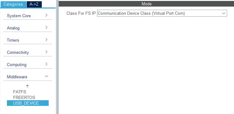
Under the “Middleware” setting I switched the “USB_DEVICE” to “Communication Device Class (Virtual Port Com)”. If I remember correctly that is basically all I had to do. All the code for receiving and transmitting data then is auto generated.
Code
Receiving Command Data
in "USB_DEVICE/App/usbd_cdc_if.c" around line 260 is a function that is called by the USB driver when a new message arrived. If the message gets longer than 32 bytes, I think it is received in multiple chunks, so the function gets called multiple times. But my protocol has only 9 bytes max, so I will not bother with that eventuality.
static int8_t CDC_Receive_FS(uint8_t* Buf, uint32_t Len)
{
  /* USER CODE BEGIN 6 */
  USBD_CDC_SetRxBuffer(&hUsbDeviceFS, &Buf[0]);
  USBD_CDC_ReceivePacket(&hUsbDeviceFS);
  USB_Serial_Received(Buf, Len); // <-- this line was added to process the received data in my code
  return (USBD_OK);
  /* USER CODE END 6 */
}
I order to make this custom function "USB_Serial_Received" known here (details of the function follow below), I have to declare it as a prototype in "Core/Inc/main.h" like this:
/* USER CODE BEGIN EFP */
void USB_Serial_Received(uint8_t* Buf, uint32_t *Len);
/* USER CODE END EFP */
and included the header "main.h" file in "USB_DEVICE/App/usbd_cdc_if.c" here:
/* USER CODE BEGIN INCLUDE */
# include "main.h"
/* USER CODE END INCLUDE */
Processing Command Data
Processing the incoming data will basically all be done in the "USB_Serial_Received" function in "Core/Src/main.c". Usually I don’t like to do too much processing in an interrupt function, but my tests indicated, that copying the raw data out to process it later in the main loop took quite some time as well, so I went for the direct route.
Here is the whole function plus the declaration of a global array to hold the extracted data:
/* USER CODE BEGIN PV */
char servo_uart[8] = {0, 0, 0, 0, 0, 0, 0, 0};
/* USER CODE END PV */
...
/* Private user code ---------------------------------------------------------*/
/* USER CODE BEGIN 0 */
void USB_Serial_Received(uint8_t* Buf, uint32_t *Len)
{
	// Set all 8 Outputs
	if (*Len == 9 && Buf[0] == 255)
	{
		for (int i=0; i<8; i++)
		{
			servo_uart[i] = Buf[i+1];
		}
	}

	// Set one Output
	else if (*Len == 3 && Buf[0] == 254)
	{
		char id = Buf[1];
		char setting = Buf[2];
		if (id < 8 && setting <= 250)
		{
			servo_uart[(int)id] = setting;
		}
	}

	// Set Cycle Time
	else if (*Len == 2 && Buf[0] == 253)
	{
		int new_cycle_time = Buf[1];
		if (new_cycle_time >= 3 && new_cycle_time <= 20)
		{
			HAL_TIM_Base_Stop(&htim4);
			htim4.Init.Period = (new_cycle_time*250)-1;
			HAL_TIM_Base_Init(&htim4);
			HAL_TIM_Base_Start(&htim4);
		}
	}

	// Echo Input Data
	CDC_Transmit_FS(Buf, *Len);
}
/* USER CODE END 0 */
The global array "servo_uart[8]" is used to hold the decoded values for the servo outputs, so they can be used further down in the main loop.
Each commands starts with a “command byte”. For that I use values of 251 and above, since they are not used in the actual payload of the command (I only set the servo outputs to values between 0 and 250). This would give me only five different commands, but since I only use three anyway, that is not a problem. The three commands are:
- Set all Outputs
Command byte: 255
Command length: 9 bytes
The bytes number 1 (byte 0 being the command byte) to 8 contain the output settings for all servo outputs “Out0” to “Out7”. This command gives me the possibility to change all outputs in one go. - Set one Output
Command byte: 254
Command length: 3 bytes
With this command I can set one specific servo output. Byte 1 in the command indicates which output should be updated (0 to 7) and byte 2 contains the new output value (0 to 250). - Set Cycle Time
Command byte: 253
Command length: 2 bytes
For every command I check if the number of received bytes fit to the expected command length and if the command byte is correct. Then I just copy the appropriate data into my global array (for the first two commands), or (for the last command) change the period value for my main timer.
I do some additional checks (no so much because I fear corrupted data, rather than making sure I don’t break anything when I accidentally send wrong data) like making sure the my output index is below 8, or the cycle time it between 3 and 20 ms.
At the end of this function I echo the received data back over the USB port. The only reason being so I have something to check, if the data (and what data exactly) was received and processed. This is mainly for debugging and could be kicked out again, once everything is working.
Main Function
And with that preparation finished, here is the main function with the infinite loop:
int main(void)
{
  /* MCU Configuration--------------------------------------------------------*/

  /* Reset of all peripherals, Initializes the Flash interface and the Systick. */
  HAL_Init();

  /* Configure the system clock */
  SystemClock_Config();

  /* USER CODE BEGIN SysInit */
  int loops = 0;
  int last_counter = 0;
  int current_counter = 0;
  char servo_out[8] = {0, 0, 0, 0, 0, 0, 0, 0};

  int start_signal = GPIO_PIN_SET;
  int end_signal = GPIO_PIN_RESET;
  /* USER CODE END SysInit */

  /* Initialize all configured peripherals */
  MX_GPIO_Init();
  MX_TIM4_Init();
  MX_USB_DEVICE_Init();


  /* Infinite loop */
  /* USER CODE BEGIN WHILE */
  while (1)
  {
    // Read counter and continue only on new value
    while (current_counter == last_counter)
    {
      current_counter = __HAL_TIM_GET_COUNTER(&htim4);
    }
    last_counter = current_counter;

    // Start Signal
    if (last_counter == 0)
    {
      HAL_GPIO_WritePin(Out0_GPIO_Port, Out0_Pin, start_signal);
      HAL_GPIO_WritePin(Out1_GPIO_Port, Out1_Pin, start_signal);
      HAL_GPIO_WritePin(Out2_GPIO_Port, Out2_Pin, start_signal);
      HAL_GPIO_WritePin(Out3_GPIO_Port, Out3_Pin, start_signal);
      HAL_GPIO_WritePin(Out4_GPIO_Port, Out4_Pin, start_signal);
      HAL_GPIO_WritePin(Out5_GPIO_Port, Out5_Pin, start_signal);
      HAL_GPIO_WritePin(Out6_GPIO_Port, Out6_Pin, start_signal);
      HAL_GPIO_WritePin(Out7_GPIO_Port, Out7_Pin, start_signal);
    }

    // Update buffered Signal Output to make sure it does not change during the duty cycle
    if (last_counter >= 100 && last_counter <= 107)
    {
        servo_out[last_counter-100] = servo_uart[last_counter-100];
    }

    // Stop Signal
    // iterating over this with a for loop takes 4.4µs instead of 1.8µs with this code
    if (last_counter == 250 + servo_out[0]) HAL_GPIO_WritePin(Out0_GPIO_Port, Out0_Pin, end_signal);
    if (last_counter == 250 + servo_out[1]) HAL_GPIO_WritePin(Out1_GPIO_Port, Out1_Pin, end_signal);
    if (last_counter == 250 + servo_out[2]) HAL_GPIO_WritePin(Out2_GPIO_Port, Out2_Pin, end_signal);
    if (last_counter == 250 + servo_out[3]) HAL_GPIO_WritePin(Out3_GPIO_Port, Out3_Pin, end_signal);
    if (last_counter == 250 + servo_out[4]) HAL_GPIO_WritePin(Out4_GPIO_Port, Out4_Pin, end_signal);
    if (last_counter == 250 + servo_out[5]) HAL_GPIO_WritePin(Out5_GPIO_Port, Out5_Pin, end_signal);
    if (last_counter == 250 + servo_out[6]) HAL_GPIO_WritePin(Out6_GPIO_Port, Out6_Pin, end_signal);
    if (last_counter == 250 + servo_out[7]) HAL_GPIO_WritePin(Out7_GPIO_Port, Out7_Pin, end_signal);

    // Blinky Light every 200ms at 50Hz
    if (last_counter == 0)
    {
      loops += 1;
    }
    if (loops == 10)
    {
      HAL_GPIO_WritePin(LED_GPIO_Port, LED_Pin, GPIO_PIN_RESET);
    }
    if (loops == 20)
    {
      HAL_GPIO_WritePin(LED_GPIO_Port, LED_Pin, GPIO_PIN_SET);
      loops = 0;
    }
  }
}
Declarations
Before the main loop there is a bunch of initialization and config calls which were already auto-generated by the IDE and I only changed one little thing. In the end of the "MX_TIM4_Init(void)" function (which is used to set up the timer), I added a command to actually start the timer using
HAL_TIM_Base_Start(&htim4);I’m not 100% sure I had to, but I had some problems at the beginning with the timer not seeming to work properly and that seemed to have solved it. I also doesn’t hurt so, whatever.
The variable declaration is pretty standard as well. Two things to point out:
- I use another array for driving the servo outputs
"servo_out[8]"and won’t use the previously global defined"servo_uart[8]"directly. The reason being, the values in the global array can change anytime during the loop and that could lead to problems. - Instead of using the macros
"GPIO_PIN_SET"and"GPIO_PIN_RESET"directly to set the output pins to 1 and 0 respectively, I declare a"start_signal"and"end_signal"variable and use those instead later on. If I have the output pins drive the servos directly the shown setting is the correct one: the signal starts with a 1 and ends with a 0, creating a positive pulse. If I want to drive the servo signals using a transistor to shift the signal level to 5 V, it is easier to invert the signal (starting with a 0 and ending with a 1, creating a negative pulse). In that case I can simply change those variables. I could use macros here instead, but maybe I want to be able to change the polarity on the fly with a USB command, so I put it like this. It needs slightly more execution time (in the order of 0.02 µs) to red the value from the variable every time I use it, but since the"HAL_GPIO_WritePin"function that use this take like 0.5 µs execution time anyway, that doesn’t really matter.
Main Loop
The Main Loop has five parts:
1. Timer Sync
    // Read counter and continue only on new value
    while (current_counter == last_counter)
    {
      current_counter = __HAL_TIM_GET_COUNTER(&htim4);
    }
    last_counter = current_counter;
What I’m doing here is reading the current timer count. I do this as long as the count value doesn’t change. Effectively the program waits at the beginning of the main loop and only runs the rest of the loop exactly once for each count value in the timer.
2. Signal Start
    // Start Signal
    if (last_counter == 0)
    {
      HAL_GPIO_WritePin(Out0_GPIO_Port, Out0_Pin, start_signal);
      HAL_GPIO_WritePin(Out1_GPIO_Port, Out1_Pin, start_signal);
      HAL_GPIO_WritePin(Out2_GPIO_Port, Out2_Pin, start_signal);
      HAL_GPIO_WritePin(Out3_GPIO_Port, Out3_Pin, start_signal);
      HAL_GPIO_WritePin(Out4_GPIO_Port, Out4_Pin, start_signal);
      HAL_GPIO_WritePin(Out5_GPIO_Port, Out5_Pin, start_signal);
      HAL_GPIO_WritePin(Out6_GPIO_Port, Out6_Pin, start_signal);
      HAL_GPIO_WritePin(Out7_GPIO_Port, Out7_Pin, start_signal);
    }
At the beginning of the whole sequence (when the counter is 0) I activate all the sensor outputs. Even if the servo value I want to transport is 0%, the program still has to create a 1 ms pulse. So no matter what, all outputs are activated at the beginning.
3. Update Buffer
    // Update buffered Signal Output to make sure it does not change during the duty cycle
    if (last_counter >= 100 && last_counter <= 107)
    {
        servo_out[last_counter-100] = servo_uart[last_counter-100];
    }
While the pulse is active, the data output values received by the USB-uart function are copied into the “work array”. This is the data the rest of the program is actually using to determine the length of the pulse. The idea is, that even if the program receives updated values, it will still finish the current cycle before dealing with them. The data copies are spread out over multiple cycles to help distribute the load a bit. One cycle is only 4 µs long, which really isn’t a lot in terms of things that can be done.
4. Signal End
    // Stop Signal
    // iterating over this with a for loop takes 4.4µs instead of 1.8µs with this code
    if (last_counter == 250 + servo_out[0]) HAL_GPIO_WritePin(Out0_GPIO_Port, Out0_Pin, end_signal);
    if (last_counter == 250 + servo_out[1]) HAL_GPIO_WritePin(Out1_GPIO_Port, Out1_Pin, end_signal);
    if (last_counter == 250 + servo_out[2]) HAL_GPIO_WritePin(Out2_GPIO_Port, Out2_Pin, end_signal);
    if (last_counter == 250 + servo_out[3]) HAL_GPIO_WritePin(Out3_GPIO_Port, Out3_Pin, end_signal);
    if (last_counter == 250 + servo_out[4]) HAL_GPIO_WritePin(Out4_GPIO_Port, Out4_Pin, end_signal);
    if (last_counter == 250 + servo_out[5]) HAL_GPIO_WritePin(Out5_GPIO_Port, Out5_Pin, end_signal);
    if (last_counter == 250 + servo_out[6]) HAL_GPIO_WritePin(Out6_GPIO_Port, Out6_Pin, end_signal);
    if (last_counter == 250 + servo_out[7]) HAL_GPIO_WritePin(Out7_GPIO_Port, Out7_Pin, end_signal);
This is the heart of the whole program. Depending on the values in the "servo_out" array, the pulse signal for each output is deactivated again. So if a output value is 0 for example the pulse is activated at timer count 0 and deactivated at timer count 250 + 0 = 250, which means a 250 * 4 µs = 1 ms pulse. On the other hand, if the output value is 250, the pulse gets deactivated at timer count 250 + 250 = 500, which means a 500 * 4 µs = 2 ms pulse. And basically everything in between.
5. Blinky LED
    // Blinky Light every 200ms at 50Hz
    if (last_counter == 0)
    {
      loops += 1;
    }
    if (loops == 10)
    {
      HAL_GPIO_WritePin(LED_GPIO_Port, LED_Pin, GPIO_PIN_RESET);
    }
    if (loops == 20)
    {
      HAL_GPIO_WritePin(LED_GPIO_Port, LED_Pin, GPIO_PIN_SET);
      loops = 0;
    }
At the end I added a bit of code that lets the LED on the evaluation board blink regularly, just so I can tell directly if the code is running or not. The blinking frequency changes with the cycle time, which I find quite nice as well.
Conclusion
And that is all for the firmware of the micro controller. I’m using another STM32 board I programmed as a ST-Link V2 debugger to flash the code on my board which works great. Also I recently got myself a digital oscilloscope for like 80 € on eBay, which is a really handy tool. I find it so helpful to visualize what the outputs of the controller are doing, if they the pulses have the length they should, etc.
I realized for example, that the “HAL_GPIO_WritePin” function (like I written before) takes over 0.5 µs to execute. This means, when I activate all 8 outputs at the beginning of the cycle it takes more than 4 ms, which is longer than on step in the timer. This means I will have a bit of variation in the pulse lengths depending on which output I’m using and what all the other outputs are set to, but I think I can live with that.