Servo Input
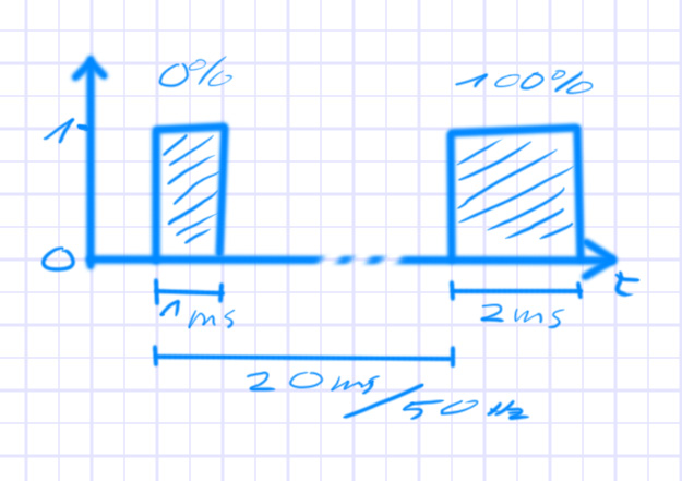
For the NERF Blaster project I want to play around with some brushless ESCs (electronic speed control). Since they are often (especially the cheap ones) are designed to be controlled by hobby remote control units, they take a “servo input”. This is basically a pulse with a length of 1ms (representing 0% input) to 2ms (representing 100% input).
Originally I believe this was a 50 Hz signal, probably due to the analog technology of old. Nowadays you can easily go close to 500 Hz (there still needs to be some gap were the signal is 0, even if you have a 2 ms pulse) and other standards exist, that use shorter pulse length (like OneShot125) to allow even higher frequencies. For quad-copters for example it makes sense to go as high as possible with the refresh rate, but I will not be needing that, so 500 Hz is plenty for me.
System Overview

The goals for this project are
- use a micro-controller to generate the 1-2ms pulses at 50 to 250Hz (I don’t even need the 500Hz)
- do at least 2 independent channels (I want to control 2 ESCs at the same time minimum)
- make a little PCB for the 3 pin connectors of the ESC (or for any servos for that matter)
- control the output signals from the PC via USB (using the build-in USB2Serial function of the micro-controller)
- have some kind of GUI with sliders to control the output signals
Micro-Controller
I will use a STM32F103 “Blue Pill” development board (even if mine is actually a black PCB), because I have one lying around. They are quite flexible to use, have decent speed and build in USB2Serial support. It might be a bit overkill for what I have in mind, but whatever.
The basic idea is to send some binary data to the STM32 to control the pulse length of the output channels. Something like “0” means a 1 ms pulse, “50” means a 1.5 ms pulse, and “100” means a 2 ms pulse. On the micro-controller that data is read and then it will use one or two of its timers to generate cyclic pulses of the required length.
Since I want to be able to control at least two individual channels, I decided to go all the way up to 8 channels, simply because the extra effort to send and read some extra bytes and control some extra outputs can’t be that big. And 8 is a nice number for a micro-controller.

Electronics
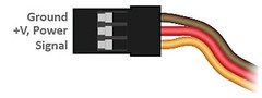
I have to mount the micro-controller to something and route the signals to some connectors. The good thing is, the default connectors of RC receivers are just 3pin 2.54 mm connectors, which I can easily put in a stripboard and don’t HAVE to design and custom PCB for or mess around with lots of cables.
The three pines on a servo connector are GND, 5V, and signal. While the “Blue Pill” can be powered by the 5V of the USB (which is convenient since I want to connect the USB anyway for the data connection), it actually runs on 3.3V and uses a step-down converted on the PCB for that. That means the signals it provides are only 3.3V on a high and the available VCC on its pin-out is only 3.3V as well (at least on my version, I think there are other designs out there as well).
I have to check, if the 3.3V signal is still enough to drive a servo or ESC. If not, I will need some extra power supply and some transistors to shift the signal level from 3.3V to 5V. But even if this works directly from USB, it will not be recommended to run more than one or two servos directly from the USB’s power, or put them on heavy load. The USB can only provide 500 mA, which is really not a lot for a servo (especially under load) and I don’t want to burn out the port on my PC or worse. For the ESCs on the other hand it will not be a problem, since get their power directly from the connected battery and only take signal and GND on the connectors.